Quadruped Robots Explained: How Robot Dogs Run, Balance, and Traverse Rough Terrain
- Four legs balance agility and stability: Quadruped robots traverse stairs, rubble, and mud that stop wheeled bases while offering wider static and dynamic stability margins than bipedal humanoids.
- Quasi-Direct-Drive (QDD) actuators: Mounting low-ratio brushless motors at the hips and driving the knees through linkages keeps distal leg inertia low for fast swing recovery and compliant impact absorption.
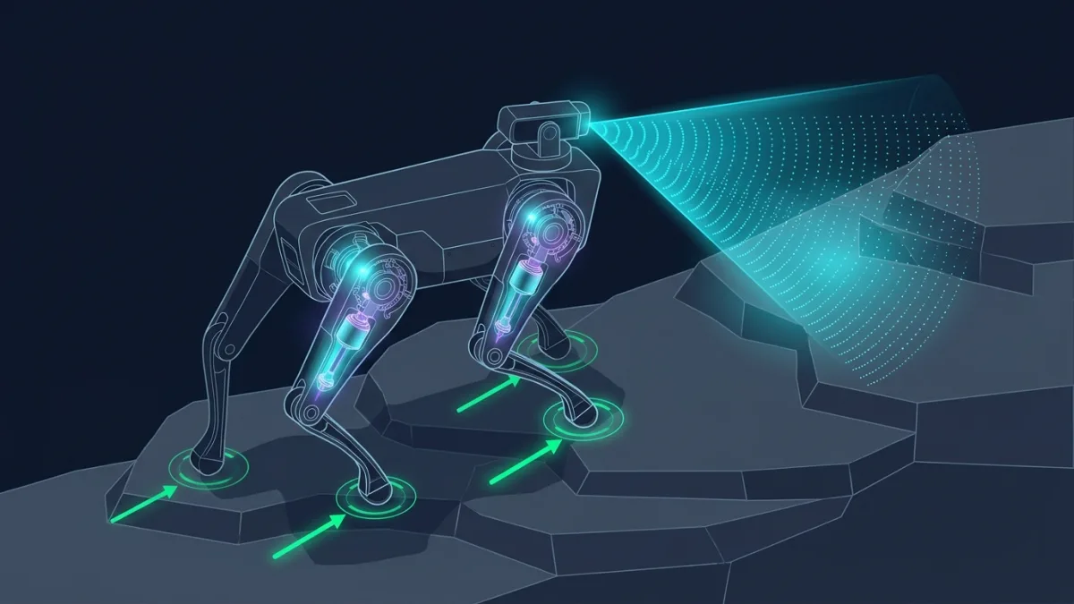
- Convex MPC and Reinforcement Learning: Modern robot dogs combine real-time ground reaction force optimization with learned terrain adaptation to climb obstacles even in total darkness.
Long before two-legged humanoid robots began walking across factory floors, four-legged quadruped robots—commonly called “robot dogs”—proved that legged machines could perform reliable daily work in unstructured industrial environments. From underground mines and offshore electrical substations to construction sites and chemical plants, quadrupeds have become the workhorses of field robotics.
What makes the four-legged morphology so effective? Compared to wheeled or tracked rovers, a legged robot does not require a continuous paved path; it needs only discrete footholds to step over pipes, curbs, cable trays, and steep staircases. And compared to bipedal humanoid robots, a quadruped possesses four points of contact, a lower center of mass, and a wide support polygon that naturally resists tipping when bumped or parked on slopes.
Mechanical Design: Why Robot Knees Look Backwards (and Why Motors Sit at the Hip)
If you inspect a commercial quadruped such as the Boston Dynamics Spot platform, the ETH Zurich ANYmal, or the MIT Mini Cheetah, you will notice that every leg shares a remarkably consistent kinematic layout with three degrees of freedom (3-DoF) per leg—twelve powered joints in total:
- Hip Abduction/Adduction (HAA): Rotates the entire leg assembly inward or outward along the roll axis, allowing the robot to widen its stance, walk sideways, and catch its balance when pushed laterally.
- Hip Flexion/Extension (HFE): Swings the upper thigh link forward and backward along the pitch axis to propel the body.
- Knee Flexion/Extension (KFE): Extends or retracts the lower shank link to control vertical ground clearance and push against the floor.
To survive repeated ground impacts without shattering gear teeth, modern electric quadrupeds rely on Quasi-Direct-Drive (QDD) proprioceptive actuators. Instead of placing a heavy motor at the knee joint—which would increase rotational inertia and slow down leg swing—engineers bolt both the hip flexion motor and the knee motor coaxially inside the upper hip housing. A timing belt, chain, or four-bar parallel linkage transmits torque down to the knee, keeping the lower leg lightweight so the foot can accelerate rapidly and sense contact forces directly through motor phase current without fragile foot load cells.
Quadruped Gaits Explained: Crawl, Trot, Pace, and Bound
A four-legged machine can coordinate its Front-Left (FL), Front-Right (FR), Hind-Left (HL), and Hind-Right (HR) legs in several distinct rhythmic patterns, known as gaits, depending on speed and terrain roughness:
| Gait Pattern | Footfall Sequence & Phase | Stance Duty Factor | Primary Engineering Use Case |
|---|---|---|---|
| Static Walk / Crawl | One leg swings at a time (FL → HR → FR → HL); 3 feet always on ground | 75% – 85% | Steep stairs, slippery rubble, or high-payload inspection where static stability is paramount |
| Diagonal Trot | Diagonal pairs move together: (FL + HR) alternate at 50% phase with (FR + HL) | 45% – 60% | Standard energy-efficient cruising gait; balances pitch and roll moments across the center of mass |
| Flying / Running Trot | Diagonal pairs alternate with a brief aerial flight phase between stances | 35% – 45% | High-speed dashing (2.5 to 5+ m/s) across open outdoor terrain |
| Pronk / Bound | Front pair (FL + FR) and hind pair (HL + HR) act in unison | 30% – 45% | Jumping across gaps, ditches, or raised vertical obstacles |
Use the interactive trotting simulator below to adjust Trot Frequency (Hz), Stance Duty Cycle (%), and Foot Clearance (cm) and observe how the diagonal leg timing diagram and foot swing trajectory respond in real time:
How Robot Dogs Balance: Convex MPC and Reinforcement Learning
During a dynamic trot, only two diagonal feet touch the ground at any instant, forming a narrow support line rather than a three-point triangle. How does the controller prevent the robot's trunk from pitching or rolling over that line? Two control architectures dominate modern legged locomotion:
1. Convex Model Predictive Control (Convex MPC)
As introduced in the landmark paper Dynamic Locomotion in the MIT Cheetah 3 Through Convex Model-Predictive Control (Di Carlo et al., arXiv:1809.02793), the controller approximates the robot's torso as a single rigid body and ignores the negligible mass of the swinging legs. At every control step (50 to 250 Hz), the computer solves a convex quadratic program over a future time horizon to compute the optimal 3D ground reaction force vector $\mathbf{f}_i = [f_x, f_y, f_z]^T$ at each stance foot while strictly obeying Coulomb friction cone constraints ($|f_{x,y}| \le \mu f_z$). Those desired foot forces are then mapped into joint motor torques via the leg Jacobian transpose $\boldsymbol{\tau} = \mathbf{J}^T(\mathbf{q})\mathbf{f}_i$.
2. Proprioceptive & Perceptive Reinforcement Learning
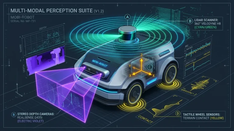
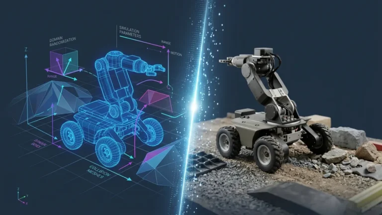
When a robot dog walks through deep mud, loose scree, or tangled underbrush, analytical friction models can break down. As demonstrated in Learning Quadrupedal Locomotion over Challenging Terrain (Lee et al., Science Robotics / arXiv:2010.11251) and Learning Robust Perceptive Locomotion for Quadrupedal Robots in the Wild (Miki et al., arXiv:2201.08117), neural policies trained via reinforcement learning combine 2.5D elevation maps from onboard LiDAR and stereo depth cameras with a history of joint encoder errors. Even if smoke or mud blinds the cameras, the policy falls back seamlessly to proprioceptive touch—inferring step edges and slip directly from leg kinematics to bridge the sim-to-real gap.
This official Boston Dynamics video shows how a quadruped robot coordinates its four legs and torso posture with a dorsal manipulator arm to open doors and grasp objects:
From my own experience
[ADD MY EXPERIENCE: Describe your observations from testing or simulating a quadruped robot (such as Unitree Go2, ANYmal, or Spot in MuJoCo/Isaac Sim) across uneven terrain.]
Sources
- Boston Dynamics Spot Official Technical Overview — Manufacturer specifications and payload architecture for the industrial Spot quadruped platform.
- Dynamic Locomotion in the MIT Cheetah 3 Through Convex Model-Predictive Control (arXiv:1809.02793) — Foundational control paper detailing convex quadratic programming for 3D ground reaction force optimization in legged robots.
- Learning Quadrupedal Locomotion over Challenging Terrain (arXiv:2010.11251) — Primary research paper introducing privileged teacher-student reinforcement learning for blind proprioceptive terrain traversal.
- Learning Robust Perceptive Locomotion for Quadrupedal Robots in the Wild (arXiv:2201.08117) — Research paper demonstrating multi-modal fusion of LiDAR/depth elevation maps with proprioceptive RL on the ANYmal quadruped.
Last updated: November 3, 2026