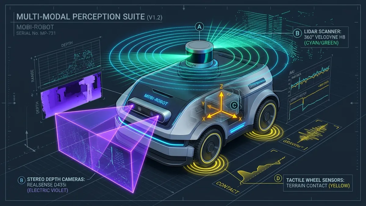
The Sensors a Robot Needs: Cameras, LiDAR, IMUs and Force Sensors
- No single sensor is enough: Robots combine external perception (cameras, LiDAR) with internal body sense (IMUs, joint encoders, and force sensors).
- Cameras vs. LiDAR: Cameras provide dense color and semantic detail for object recognition, while Time-of-Flight LiDAR delivers lighting-invariant 3D geometry.
- IMUs and Force/Torque sensors run at hundreds to thousands of hertz, enabling instantaneous balance recovery and compliant, damage-free manipulation.
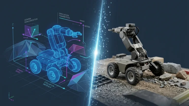
Before a robot can plan a path across a warehouse floor or pick up a fragile circuit board, it must answer two fundamental questions: Where am I relative to the surrounding world? and What forces is my body experiencing right now? Because every physical transducer has blind spots, Physical AI platforms rely on a complementary suite of cameras, LiDAR, inertial measurement units (IMUs), and force/torque sensors.
Robotics engineers divide these sensors into two functional groups: exteroceptive sensors, which measure the external environment (distance, light, and surface geometry), and proprioceptive sensors, which measure the internal physical state of the robot itself (joint angles, tilt, acceleration, and contact wrenches). Let us examine how each sensor works and why modern robotics architectures fuse them together.
1. Vision and Depth Cameras: The Semantic Eyes of a Robot
Standard monocular RGB cameras capture dense grids of red, green, and blue pixels at 30 to 90 frames per second. While passive cameras are inexpensive, compact, and essential for feeding Vision-Language-Action (VLA) models, a single 2D image flattens three-dimensional depth. To recover metric distance ($Z$) for every pixel, robots use three primary depth-camera architectures:
- Passive and Active Stereo Vision: Two horizontally separated global-shutter cameras capture synchronized frames and compute pixel disparity $d$ across a known baseline $B$, yielding depth via $Z = (f \cdot B) / d$. Active stereo cameras add an infrared dot projector to provide artificial texture on blank white walls.
- Structured Light: Projects a known infrared pattern onto nearby objects and calculates depth from geometric pattern distortion—accurate at close range indoors, but easily washed out by direct outdoor sunlight.
- Indirect Time-of-Flight (iToF) Depth Cameras: Flood the scene with modulated infrared light and measure the phase shift of the reflected wave at every pixel simultaneously.
2. LiDAR: Lighting-Invariant 3D Geometry
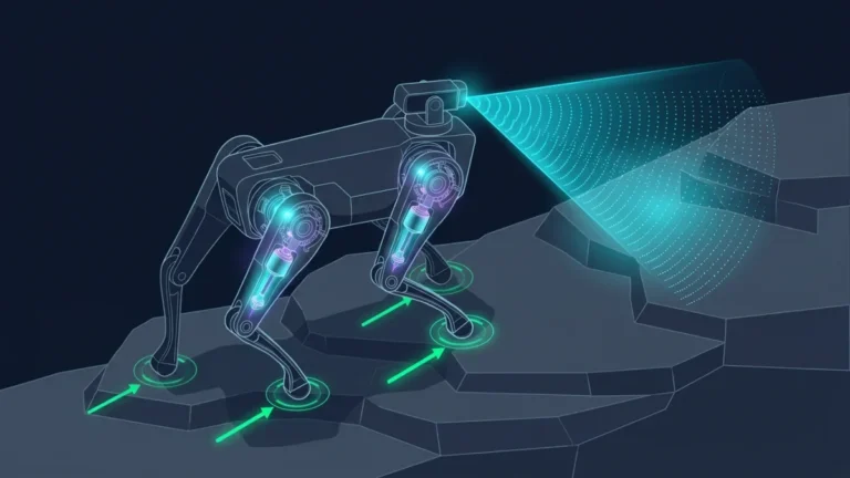
When an autonomous mobile robot or outdoor quadruped navigates a long corridor, a dark warehouse, or bright midday sun, passive cameras can struggle with dynamic range and depth noise beyond a few meters. LiDAR (Light Detection and Ranging) solves this by firing narrow eye-safe laser pulses and measuring the exact round-trip time of flight ($\Delta t$) at the speed of light ($c$), computing distance as $d = (c \cdot \Delta t) / 2$.
As explained in the Ouster / Velodyne technical guide to digital LiDAR, multi-beam 3D LiDAR sensors generate hundreds of thousands of precise $(x, y, z, \text{intensity})$ points per second across a 360-degree field of view. Because LiDAR supplies its own active laser illumination, its geometric accuracy remains consistent in total darkness and across 50-to-100-meter ranges—making it the backbone of Simultaneous Localization and Mapping (SLAM).
3. Inertial Measurement Units (IMUs): The Robot’s Inner Ear
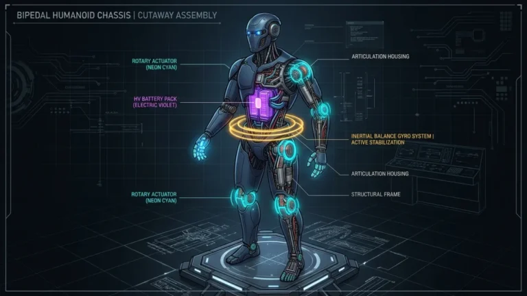
Cameras and LiDAR typically update at 10 to 60 Hz—far too slow to stabilize a humanoid robot whose ankle or hip is beginning to tip. To maintain balance between visual frames, every mobile robot houses at least one Inertial Measurement Unit (IMU) mounted rigidly to its pelvis, torso, or sensor head.
A 6-axis micro-electro-mechanical (MEMS) IMU—fabricated by semiconductor manufacturers such as Bosch Sensortec—combines a three-axis linear accelerometer (measuring specific force including gravity along $X, Y, Z$) with a three-axis gyroscope (measuring angular velocity in degrees or radians per second around roll, pitch, and yaw) at 200 to 2,000 Hz.
Because integrating raw gyroscope and accelerometer signals over time accumulates mathematical drift from thermal bias and vibration noise, robots never rely on an IMU alone for long-term position. Instead, an Extended Kalman Filter (EKF) integrates the IMU for instant millisecond posture updates and continuously corrects drift whenever a camera or LiDAR frame arrives.
4. Force/Torque and Tactile Sensors: Physical Touch
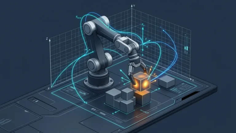
The moment a robot’s gripper contacts a metal bolt or slides a plug into a socket, rigid position control becomes dangerous: a two-millimeter calibration error can generate hundreds of newtons of jamming force. To interact safely with rigid surfaces, manipulators rely on 6-axis Force/Torque (F/T) transducers mounted at the wrist or ankle, alongside distributed fingertip tactile arrays.
As documented in the ATI Industrial Automation Multi-Axis Force/Torque Sensor technical reference and academic reviews of robotic tactile sensing (arXiv:1909.03550), a 6-axis F/T sensor uses silicon or metallic strain gauges arranged on flexure beams to measure all three orthogonal forces ($F_x, F_y, F_z$) and all three moments/torques ($T_x, T_y, T_z$) simultaneously at kilohertz rates. Local Edge AI microcontrollers often sample these tactile arrays directly in the hand to trigger instant slip reflexes.
| Sensor Modality | Typical Update Rate | Primary Strength | Key Failure Mode / Limitation |
|---|---|---|---|
| RGB-D / Stereo Camera | 30 – 90 Hz | Rich semantic color, object recognition, dense close-range 3D depth | Struggles with specular glare, transparent glass, darkness, and long range |
| 3D Time-of-Flight LiDAR | 10 – 20 Hz | Accurate long-range 3D point clouds in both darkness and sunlight | Lower spatial resolution than cameras; no RGB color; higher cost/power |
| 6-Axis MEMS IMU | 200 – 2,000 Hz | Microsecond latency orientation and angular velocity for balance | Integrates bias drift rapidly without external visual/kinematic correction |
| 6-Axis Force/Torque & Tactile | 500 – 2,000 Hz | Direct measurement of contact forces, surface normal, and part slip | Measures only upon physical contact; vulnerable to mechanical overload |
Sensor Calibration and Coordinate Transforms
Having four sensor types on one robot is useless unless the software knows the exact three-dimensional rotation and translation ($SE(3)$ homogeneous transform) between the camera optical center, the LiDAR rotor, the torso IMU, and the fingertip pad. Frameworks such as the ROS 2 TF2 Transform Library maintain a real-time kinematic coordinate tree so a 3D point detected in the camera frame can be transformed accurately into the robot wrist frame for grasping.
This official Boston Dynamics video demonstrates how humanoid grippers integrate onboard cameras and tactile force sensing to grasp industrial components:
From my own experience
[ADD MY EXPERIENCE: Describe your experience calibrating a depth camera, LiDAR, or IMU on a robot platform and what sensor artifacts you had to filter out.]
Sources
- What is LiDAR? Digital 3D LiDAR Technical Overview (Ouster / Velodyne) — Industry technical reference explaining Time-of-Flight laser ranging and 3D point cloud generation.
- Multi-Axis Force/Torque Sensor Technical Documentation (ATI Industrial Automation) — Manufacturer engineering reference for 6-axis wrist and ankle force/torque transducers in robotics.
- Tactile Sensing for Dexterous In-Hand Manipulation in Robotics (arXiv:1909.03550) — Peer-reviewed technical paper covering optical, piezoresistive, and capacitive tactile sensors for robotic hands.
- ROS 2 TF2 Coordinate Transform System Documentation — Official documentation on managing multi-sensor coordinate frame trees in robotic software stacks.
- Bosch Sensortec MEMS Motion Sensors & IMUs — Manufacturer technical reference for 6-axis and 9-axis MEMS inertial measurement units.
Last updated: November 3, 2026